My plants are unhappy. I go away a lot and they don’t get looked after. I figured I could do something about this.
First off, I should own up to having solved this problem before. Mk1 used one of these commercially available things

and a water pump smashed out of a battery powered kids water pistol, a bit of hose and a phone charger. It was plugged into the wall via a timer plug so it was only powered for 15 minutes a day, but the probes still corrode way too fast to be useful long term and the pump draws a lot of electrics (800mA for up to a minute at a time) so it’s constrained to live near a socket. In light of this first success my requirements have been refined. Mk2 must:
1. Water plants when they need it (see how that one’s top of the list)
2. Be able to run from (cheap!) solar power
3. Not electrolyse the soil probes away
4. Cost less than a commercially available alternative
Now, I’ve seen this kind of thing done loads on hackaday. People just grab an arduino/pi/whatever and buy a solenoid valve and call it good. Well requirement 2 kinda dumps on the pi, probably the arduino too, and 2 and 4 both rule out the 12/24V solenoid valve. But we still need some kind of intelligence to meet #3 by limiting the time we run current through wet dirt.
Enter the PIC. It draws like 20 microAmps or something in sleep mode, and even with everything running it’s hardly what you’d call thirsty. These things are ideal for solar power. I went for the 12f683 because it’s small and cheap, but almost any would do.
We also need a bespoke power supply. This part was fairly easy. It’s 4 solar garden lights, costing £1 each, with the guts removed. Maplin part# N08FX to be precise.

Each contains a AAA NiMH cell and a crap solar panel (and a white LED and switch, together worth about 80p, that I get to keep). The solar cells are connected in series, the AAAs are connected in series, and the solar cells charge the batteries through a diode so they can’t drain at night. I added a USB connector to make wiring easy and universal.
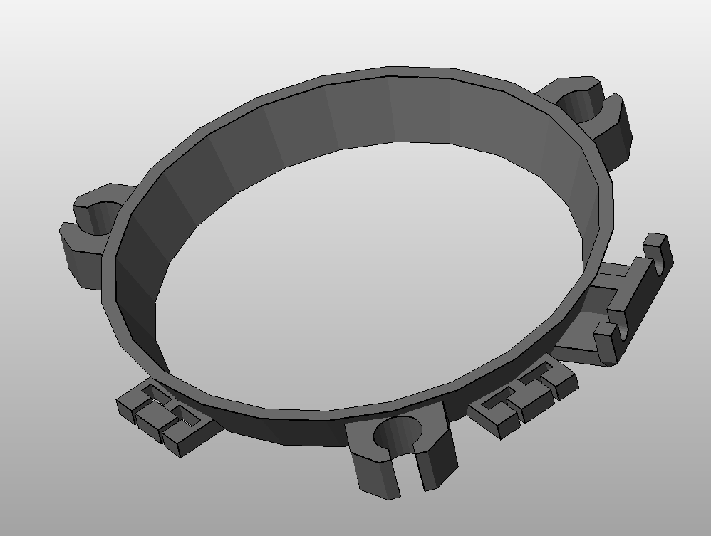
I figured a custom stand would be a nice touch, so I drew and printed this too.


Now we’re going to need a valve that can control water with 5 Volts and, to be sensible, not draw much more than an Amp. I searched extensively and found, never mind requirement #4, you just can’t buy that. This is where the project hit its first wall. I’d have to invent a valve.
I played with coils of wire wound on steel bolts lifting steel ball bearings. The results were encouraging, so I started trying to design a valve seat that a ball bearing would seal against. I tried moulding stuff out of silicone sealant but the results were too grabby for the solenoid to pull against. I tried drilling very very neat holes in all sorts of things but nothing was perfectly round enough to seal. I tried 3d printing parts but they all leaked, no matter what I tried. I tried 3d printing something that would take an o-ring that would seat a ball bearing. No joy – the o-ring always distorted just enough to leak.
Then, one day, as I was washing the dishes and ran out of detergent I spotted something. The cap on the bottle had a perfectly made toroidal hole that would work perfectly. A quick bit of drawing and I had a valve assembly that would open and close and control water with electricity. This felt like a hell of an achievement. I’m still quite proud of it.


I left it for a while to see that it held water long term, and realised the ball bearing I’d used wasn’t going to work. It had rusted badly in a week. A quick search threw up a ball that is stainless but still magnetic, (that’d be 420 stainless), so I ordered a pack of 10. It worked, but not as well. Anything over an inch or two of water and the attraction was too weak to pull against the pressure. So I unwound half of the coil, snipped it and re wound it in parallel with other half to give some more Amp-turns. I don’t know how many turns it is but now the coil draws about 650mA and can open the valve under 4 inches of water, which is enough.
The coil is wound on a screw between two 3d-printed plastic discs. This screw is threaded into a little cylindrical thingy that sits in the neck of a regular cut down drinks bottle. With the dish soap bottle cap screwed on, turning the coil assembly with a screwdriver adjusts the clearance between the armature and the ball bearing so I don’t need to worry about the tolerances on those plastic parts. Simple, right?
Now that all works, it was time to figure out the logic. I wanted to be able to adjust the dryness of soil at which we decide to water, so I’d need some kind of trim pot, but how big? I stuck some screws in plant pots a few cm apart and found as expected wet soil is low resistance and drying soil can be anywhere up to 200k, but is usually about 50k at the point when you’d start to feel sorry for the plant. I went for a 100k because I had that in the parts bin. Ideally would be twice that but meh. It’ll work.
Still the PIC leaves many choices of implementation because it has so many peripherals to choose from. Do I use an ADC with the pot providing a reference voltage? Or a comparator? Or some other weird exotic with the analog inputs? In the end I chose the comparator because I understood that part of the datsheet after only 4 read throughs. That’s simpler than anything else in there…
I set about writing some code to set up all the peripherals on the pic (most of the code) and then the actual working bit (not so much). The plan is for the PIC to wake up from sleep, apply power to the probes, wait half a second for the potentials to settle down (I’d noticed drift when using a meter), then if soil resistance > pot resistance open the valve for 2 seconds. Then power off the probe voltage and comparator (important!) and sleep again.
2 seconds is enough – that lets about a teaspoon of water out, so it won’t take many cycles to saturate even the driest of pots.
The pic is clocked internally and wakes from sleep using the watchdog timer interrupt. The longest that can run is 272 seconds – about 5 mins. There’s no need to wake up that often, so I just made it sleep twice. This means it wakes and runs the test every 9 minutes.
I also wanted some kind of “calibration mode” so that I could set the pot to a sensible value without waiting 9 minutes after every tweak to see if it was right. So on waking up (or on power on) the PIC checks an input for the presence of a jumper link that sets “calibration mode”. If this is present the sleep cycle is swapped for a 2 second delay loop, meaning the test gets run every 2-ish seconds. Combined with a LED in parallel with the coil this should let me set up the device in a sensible amount of time, with or without the valve connected.
I wrote all the code while my PIC programmer was on order. I’d always borrowed one before but figured it was time.
When it arrived I breadboarded up a test circuit and was amazed to find the code was really nearly right. All I’d done was forget to put the correct delay value back in the delay loops after simulating with an artificially shortened one. One small change and it was working! When has PIC assembly EVER worked second time?! I’m super proud of that too!
So to stripboard.

I threw this together with a micro USB socket for power (see what I did there? So you can use a phone charger instead of solar if you want…) and remembered to add a diode so the flyback from the valve doesn’t toast the PIC. I knew to do that because I remember feeling the shocks when playing around testing the valve with wet hands. It tingles…
The PIC drives a MOSFET to switch the high current to the valve. The probe and valve connect on pin headers for convenience.
The soil resistance probe is just a pair of stainless screws through a bit of PLA. Nothing to see there.

I knocked up a little bottle stand and channel for the water out of PLA also, and set it in place. It works, as designed, amazingly. Its legs are the stands recycled from the garden lights I used in the power supply. The board hangs off the side of the stand and some ugly trailing wires lead off via strain reliefs to the solenoid and probes.


In the video below the part of the plant is being played by a glass, because it’s winter and there are no plants really left to water. You’ll have to take my word about the soil probe working properly. This is with the test jumper installed, so cycling constantly. In run mode there’s a 9 minute wait, but that doesn’t make good tv.
The solar cells have no trouble keeping the batteries topped up, and they in turn have no trouble feeding 600mA for 2 seconds every now and then. I think they’d struggle with anything more hungry than a PIC, though. It’s been fine looking after my chili plant for 2 months now 🙂

Pingback: Solar Powered Circuit Waters Your Plants
Pingback: Solar Powered Circuit Waters Your Plants - Tech key | Techzone | Tech data
Fine work, fine work indeed. I like how you’ve explained your thought process through the design. Recently I’ve got myself a 3D printer and am looking to get involved with small projects like this. Any chance you could post the schematics? I should be alright for figuring out the code.
LikeLike
I’ll try to complete the BOM at some point, but can’t right now. Here are the stl’s to get you started or inspired: http://www.thingiverse.com/thing:538315 and http://www.thingiverse.com/thing:538325
LikeLike
Ahh good stuff, I was going to design them myself as you provided the Maplin part numbers but this will save some time. I’m sure you’ll see my build on Thingiverse soon
LikeLike
I would suggest a few more tags PIC 12f683 Micro
LikeLike